Components#

Propellers (Props)#
Firstly, the things that create lift, the propellers.
Warning
While this is the first section, this should always be put on LAST only after all other checks have been performed.
Danger
Always check your surroundings and ask somone with experience to check before putting on propellers for maiden flight. Propellers can gravely injure people.
 Betaflight default X-frame quadcopter prop configuration
You would notice that the Motors marked 1 and 4 spin clockwise and the Motors marked 2 and 3 spin anticlockwise. Before placing the propellers, ensure that the correct CW/CCW propellers are used for the correct motors.
Tip
Some motors, typically older ones, come with self tightning nuts instead of locknuts. If the motors spin clockwise, the nut will be tightened anticlockwise(and vice versa). This prevents the propellers from loosening during flight.
Different frame configurations will have different motor directions. When in doubt, refer to the documentation on the flightstack(betaflight/PX4/Ardupilot) itself.
Power Distribution Board (PDB)#
Supplies power from the battery to the motors and converts the battery voltage to 5V for the flight controller, regulates power input to prevent the electronics onboard from damaging levels of power. The PDB should be orientated such that the big solder pads for the battery terminals should be mounted in the right orientation so that the battery leads can be easily accessed.

Certain PDBs have S1,S2,S3,S4 connections which can be used to wire up motor PWM inputs. In this case, ensure that the S1,S2,S3,S4 corresponds to Motor1,M2,M3,M4. A ribbon cable or wire harness is used to connect the motor inputs to the main flight controller. However the purpose of this is to simplify wiring, there are ports to connect the motor inputs on the flight controller itself.
Motors#
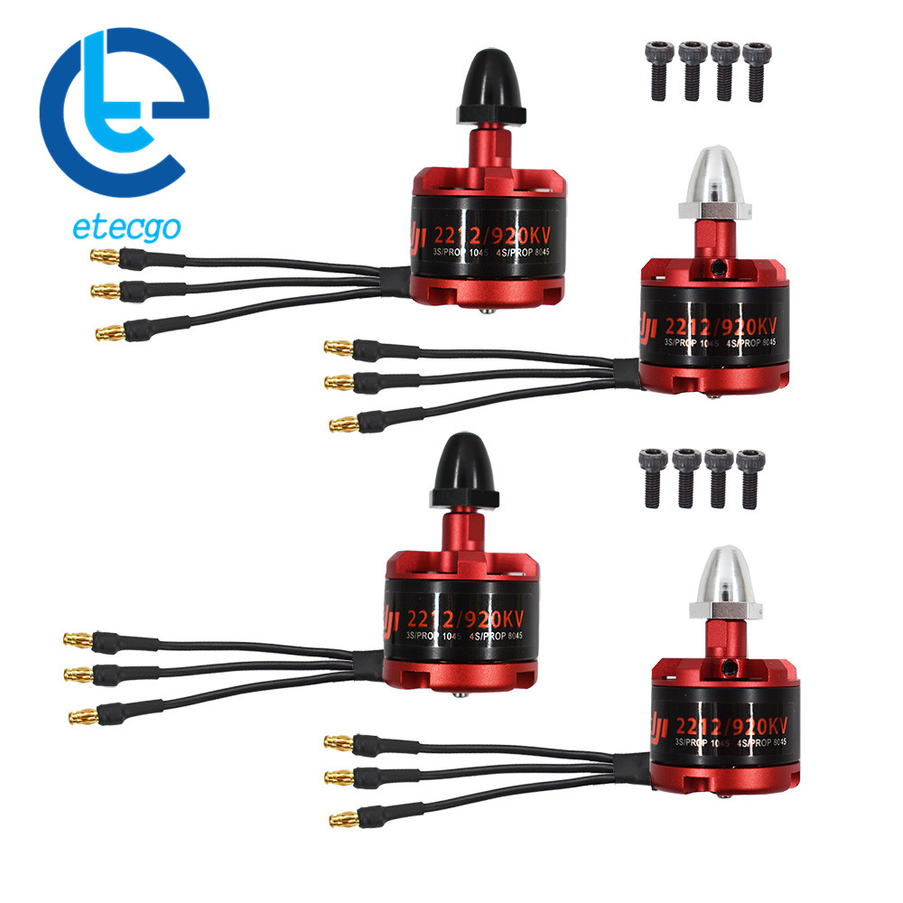
The Motors spin and generate thrust when used with the propellers. They have CW(clockwise) and CCW(Counter clockwise) orientations denoted by the colored screw caps which is threaded in the opposite direction from the rotation to self tighten and prevent propellers from flying out.

If the motor spins in the wrong direction
Swap any of the 2 motor wires
Electronic Speed Controller (ESC)#
These circuits help to regulate the speed of the motors, they take a signal from the flight controller and draw power from the Battery to drive the motor.
For smaller drones, you can find an esc all in one combined with a PDB or even built into the FC but larger drones usually have standalone ESCs for each motor due to the high power drawn.
| 4 in 1 ESC Board | Standalone ESC |
|---|---|
 |
 |
On Standalone ESCs, There will be 3 motor wires on one side of the board, and 4 or 5 wires on the other side of the board. On the other side with 4 or 5 wires, two of the wires are for battery voltage and battery ground and will be soldered to the PDB. These wires are thicker than the other wires to carry more current. The other wires are for signal,ground and sometimes telemetry. The signal should be plugged into the S1/S2/S3/S4 ports respectively and the ground can be plugged into any ground port.

Batteries (Lipo)#

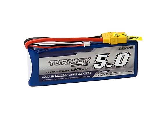
The batteries come with many different chemistries but generally we use the term LiPos (short for Lithium Polymer).
LiPos have a high rate of discharge which allows the motor to suck more current than regular batteries. This is made possible by the low resistance which is essential for the application of drones due to the high current that is drawn by the motors. As a result, a single short across the positive and negative wires is enough to kill the battery and cause an electrical fire due to the low internal resistance unlike AA/AAA batteries. Special precaution has to be taken when handling lipos to prevent puncture of cells or overcharge/discharge.
Discharging#
A single lipo cell usually has a voltage of 4.2V when full and 3.3V when empty. Overdischarging or overcharging results in the battery spoiling. LiPos have a maximum discharge rate which can be calculated from the C rating on the battery using this equation:
Charging#
In terms of charging, the safest rate to charge lipos is at 1C or 1A per 1000mah(battery capacity). So a 500mah battery would charge at 0.5A. Different manufacturers can specify different maximum charge and discharge rates for the battery but to preserve battery health a charge rate of 1C is advised.
Lipo chargers allow for charging to HV(4.35V instead of 4.2v) and some do not automatically set a safe current/voltage when charging so do be careful about that.
Storage#
For long term storage, lipos have to be discharged or charged to 3.8V which is slightly above the nominal voltage of 3.7V.
This is known as storage charging.
Radio Controllers/Transmitter#
This transmits a radio signal which is picked up by the receiver on the drone.

Radio controllers can have a module bay to add different transmitter modules.

Most radio controllers can transmit around 6-12 channels with higher end controllers having up to 18 or more channels. Each channel has an analog value and corresponds to one control such as pitch, yaw or something else. To reduce the need of having one signal and ground wire for each individual channel, protocols are used to transmit multiple channels on a single pin/wire (with 1 ground) such as sbus, ppm, cppm, etc. Do note that the different protocol eg ppm,sbus might need to be defined in both the flight controller software and on the controller itself. Documentation on the configuration required can be found by searching individual recievers and radio controllers.
Receivers#
Receivers receive the radio input transmitted by the radio controller.

There are many different transmission protocols made by different manufacturers such as Frsky,Flysky,Futaba,etc. All of which require a compatible transmitter(on the radio) and receiver talking on the same protocol. Even within a same manufacturer, there are different protocols that are incompatible with each other!
Configuration can be done on the flight controller software(betaflight), and the radio transmitter and varies on different manufacturers.
Flight Controller (FC)#
The Flight Controller is the brain/CPU of the drone, it controls the drone movements and always contains a usb port for connection to a PC for configuration.

Matek F405 Flight Controller
The first thing to notice is the arrow located on the board. The arrow points towards the front of the drone. The FC should be mounted in the correct orientation. Conveniently, this board has the pins labelled, but normally this will be indicated in the online manual. The important ports will be explained in greater detail below. Reading the manual of a FC is essential for understanding in all situations.
The S1,S2,S3,S4 pins indicate the respective ESC PWM cables that needs to be connected with respect to the pins in the betaflight/flightstack configuration. While depending on the receiver and configuration TX,RX,SBUS pins can be used.
Newer FCs may come in a set with a 4 in 1 ESC, both having matching connectors and cables to ease connection of the FC to ESC
Connections (WIP)#
![]()
In order of power coming out from battery. two battery connector wires(positive and negative) are connected to the PDB.
ENSURE BATTERY POLARITY IS CORRECT BEFORE PLUGGING IN

The PDB is then connected to the four motors each with 3 wires (in a all in one ESC board). In a standalone PDB, the power (±) leads are connected individually to the PDB and the motor PWM inputs are connected either directly to the Flight controller. The Flight Controller requires connection from the 5V/Ground and the PWM motor inputs minimally. The Receiver is connected to the Flight Controller.
And thats it!!! With this connections and after configuration your drone should be able to fly.